Blower motor
Blower motor
The fan creates the necessary air-mass flow in the climate control. The fan consists of the fan motor, the fan wheel, the fan output stage and the housing.
Functional description
At the fan output stage, the control module of the integrated automatic heating / air-conditioning system (IHKA control module) specifies the voltage for the fan motor. The specified voltage is output by the IHKA control module as a signal on the LIN bus.
Depending on this control signal, the fan motor is activated by the fan output stage.
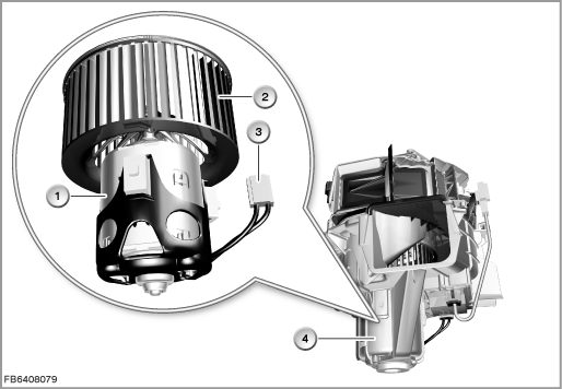
Index |
Explanation |
Index |
Explanation |
|---|---|---|---|
1 |
Blower motor |
2 |
Fan wheel |
3 |
2-pin plug-in connection |
4 |
Fan of the climate control |
Structure and inner circuit
The fan motor is an electric motor.
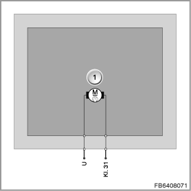
Index |
Explanation |
Index |
Explanation |
|---|---|---|---|
1 |
Blower motor |
|
|
Pin assignments
Pin |
Explanation |
|---|---|
Terminal 31 |
Terminal 31, earth connection for fan output stage |
U |
Activation of the fan output stage |
Target values
Observe the following target values for the fan motor:
Variable |
Value |
|---|---|
Voltage range |
9 to 16 V |
Maximum current consumption |
30.5 ± 1.5 A |
Temperature range |
-40 to 85 °C |
Diagnosis instructions
Failure of the component
If the fan motor fails, the following behaviour is to be expected:
- Fault memory entry in the IHKA control module
- Fan switched off.
General information
The fan output stage has diagnostic capability. The corresponding diagnosis information is transferred across the LIN bus to the IHKA control module and evaluated there. If it is likely that the fan output stage will overheat, the output voltage is reduced, which leads to reduced fan output.
No liability can be accepted for printing or other faults. Subject to changes of a technical nature