Sliding panel drive
Sliding panel drive
The sliding panel drive is installed near the centre of the roof from below on the frame for the slide/tilt sunroof.
The drive for the sliding panel and wind deflector consists of an electric motor with reduction gear.
The switch for the slide/tilt sunroof is located in the roof function centre (FZD). The function of the slide/tilt sunroof control module has also been integrated into the FZD control module.
The slide/tilt sunroof is driven by the slide/tilt sunroof drive.
Functional description
If the FZD control module receives a request for the sliding panel or wind deflector, it activates the electric motor. The electric motor is supplied with voltage (terminal 30) via a relay integrated in the roof function centre.
There are 2 Hall sensors integrated in the electric motor. The Hall sensors pick up the motor revolutions. The Hall-sensor signals are forwarded to the FZD control module.
The Hall-sensor signals indicate to the FZD control module the positions of the sliding panel and wind deflector. In addition, the closing speed of the slide/tilt sunroof is used to calculate the closing power in the control module.
The mechanical forces change with ambient temperature and ageing. Consequently, the required closing force and anti-trap function are adjusted each time the sunroof closes.
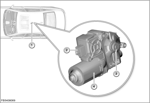
Index |
Explanation |
Index |
Explanation |
|---|---|---|---|
1 |
Sliding panel drive |
2 |
6-pin plug-in connection |
3 |
Reduction gear |
4 |
Electric motor |
The wind deflector is extended, depending on the road speed. The wind deflector has 2 positions:
- Wind deflector completely extended (also referred to a ”low-speed position”)
- Intermediate position (also referred to a ”high-speed position”)
When the sliding panel is fully open, the wind deflector extends fully with a net if the slide/tilt sunroof is more than approx. 1/3 open. The wind deflector is extended by the sliding panel drive. To do so, the sliding panel is moved on by the sliding panel drive in the non-visible area.
As of a certain speed (above 130 km/h), the wind deflector is moved from the position ”completely extended” into the intermediate position (high-speed position).
Below a certain driving speed (below 100 km/h), the wind deflector is once again completely extended.
To prevent the wind deflector from extending and retracting in a haphazard manner, the wind deflector is actuated with a time lag.
Safety functions:
- Maximum motor run time
If the motor run time for one direction is longer than 15 seconds, the FZD control module switches off the sliding panel drive. - Overheating protection
Heating of the electric motor is calculated in the FZD control module. As of a certain temperature threshold, the FZD control module switches off the sliding panel drive. - Blocking protection
If the Hall impulses from the electric motor fail to arrive for longer than 500 milliseconds, the FZD control module switches off the sliding panel drive.
Structure and inner circuit
The sliding panel drive is connected to the FZD control module by means of a 6-pin plug-in connection.
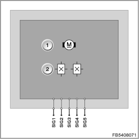
Index |
Explanation |
Index |
Explanation |
|---|---|---|---|
1 |
Electric motor |
2 |
Hall sensors |
Pin assignments
Pin |
Explanation |
|---|---|
SIG1 |
Terminal 30 (power supply) or terminal 31L (load earth), depending on the activation (open or close) |
SIG2 |
Terminal 30 (power supply) or terminal 31L (load earth), depending on the activation (open or close) |
SIG3 |
Signal from Hall sensor 2 |
SIG4 |
Earth connection for the Hall sensors (via FZD control module) |
SIG5 |
Signal from Hall sensor 1 |
1 pin not used. |
|
Target values
Observe the following target values for the sliding panel drive:
Variable |
Value |
|---|---|
Power supply |
9 to 16 V |
Maximum current consumption |
10 ± 0.2 A |
Maximum short-term (1 second) current consumption with blocking |
26 A |
Temperature range |
-40 to 80 °C |
Diagnosis instructions
Failure of the component
If the sliding panel drive fails, the following behaviour is to be expected:
- Fault memory entry in the FZD control module
- Check Control message via symbol in the instrument cluster (KOMBI)
- Slide/tilt sunroof drive and sliding panel drive inoperative, i.e.: the slide/tilt sunroof and sliding panel remain in their current positions.
No liability can be accepted for printing or other faults. Subject to changes of a technical nature