Coolant pump for intercooler
Coolant pump for intercooler
Due to turbocharging and the compact arrangement of the turbocharger in the V chamber, the N63 engine develops a great deal of heat. Accordingly, a great deal of significance is attached to cooling. Furthermore, indirect charge air cooling where the charge air is cooled across an air-coolant heat exchanger has been developed for the first time. The engine and charge air cooling have 2 separate coolant circuits.
The engine control module is also integrated in the cooling circuit for charge air cooling.
Functional description
The electric coolant pump works according to the principle of a centrifugal pump. The coolant pump is integrated in the cooling circuit (low temperature) and is used for charge air cooling. Communication between the coolant pump and the engine management system takes place across the LIN bus. This provides the engine-speed specification and the current pump speed as well as other pump variables are read out.
The following values are used for activation:
- Outside temperature
- Difference between charge-air temperature and outside temperature
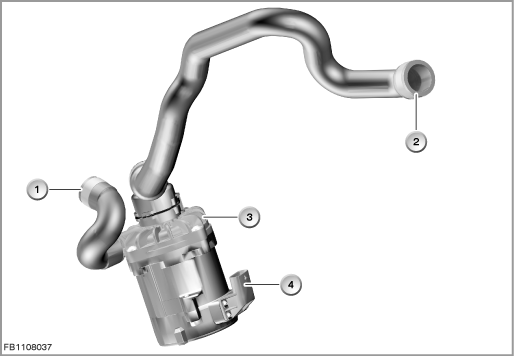
Index |
Explanation |
Index |
Explanation |
|---|---|---|---|
1 |
Coolant pump for intercooler |
2 |
Connection to air-coolant heat exchanger |
3 |
Connection from expansion tank for intercooler |
4 |
4-pin plug-in connection |
The coolant pump receives the specified target value from the engine management system across the LIN bus. The following pump variables are provided:
- Current pump speed
- Current consumption
- Voltage
- Temperature of the electronic evaluation unit
- Fault states
Structure and inner circuit
The LIN bus is a single-wire bus with a maximum data rate of 20000 bit/s. The LIN bus is based on the principle of master controller and slave, i.e. all communication is initiated by the master controller. The master controller sends a message header; the addresses slave responds with the data. The data sent by the slave are available to both the master controller any the other slaves.
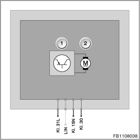
Index |
Explanation |
Index |
Explanation |
|---|---|---|---|
1 |
Electronic evaluation unit |
2 |
Coolant pump drive |
Pin assignments
Pin |
Explanation |
|---|---|
Kl. 31L |
Load ground |
LIN |
LIN bus |
Kl. 15N |
Terminal 15, power supply |
Kl. 30 |
Terminal 30, power supply |
Characteristic curve and target values
The coolant pump works in the speed range from 24 to 6000 rpm. The permitted coolant temperature lies between -40 °C and 128 °C.
The hydraulic data depend on the temperature. Above all at very low temperatures, the viscosity of the coolant has a great influence on the maximum speed and hydraulic values.
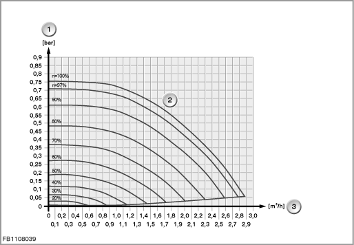
Index |
Explanation |
Index |
Explanation |
|---|---|---|---|
1 |
Differential pressure |
2 |
Characteristic curves for pump speed at coolant temperature 80 °C |
3 |
Volumetric flow |
|
|
Observe the following target values for the coolant pump for the intercooler:
Variable |
Value |
|---|---|
Voltage range (full power output) |
12.5 to 16 Volts |
Voltage range (reduced power output) |
8 to 12.5 Volts |
Power output |
50 watts |
Maximum current consumption in normal operating mode |
6.5 A |
Temperature range of coolant temperature |
-40 to 128 °C |
Temperature range |
-40 to 140 °C |
Diagnosis instructions
Failure of the component
If the coolant pump for the intercooler fails, the following behaviour is to be expected:
- Fault memory entry in the engine control module
- Emergency operation of the coolant pump for intercooler if a voltage of at least 0.6 Volts is applied at the input for emergency operation: Maximum supply rate
General information
The following diagnostic procedures are available for the coolant pump:
- Engine speed monitoring
- Signal cable for emergency operation
- Shutdown of coolant pump
- Power reduction of coolant pump
No liability can be accepted for printing or other faults. Subject to changes of a technical nature