Turbocharger coolant pump
Turbocharger coolant pump
Due to turbocharging and the compact arrangement of the turbocharger in the V chamber, the N63 engine develops a great deal of heat. Accordingly, a great deal of significance is attached to cooling.
The bearing seats of the turbocharger are cooled separately by the turbocharger coolant pump. This is done specifically to ensure that heat continues to be withdrawn from the turbochargers after stopping the engine.
The turbocharger coolant pump is integrated in the engine cooling circuit.
Functional description
The electric turbocharger coolant pump works according to the principle of a rotatory pump. The turbocharger coolant pump is located at an angle behind the expansion tank of the cooling circuit for charge air cooling. The engine management system activates the turbocharger coolant pump directly (not via the LIN bus as in the case of the coolant pump for the intercooler).
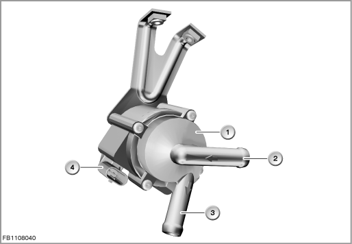
Index |
Explanation |
Index |
Explanation |
|---|---|---|---|
1 |
Turbocharger coolant pump |
2 |
Connection from the turbochargers |
3 |
Connection to the engine cooling circuit |
4 |
3-pin plug-in connection |
The electric turbocharger coolant pump is activated taking account of the following variables:
- Coolant temperature at the engine exit
- Engine oil temperature
- Injected volume of fuel
The injected volume of fuel is used to calculate the heat contribution to the engine. The function is similar to heat management on 6-cylinder engines. The after-run of the turbocharger coolant pump can last up to 30 minutes. To improve the cooling effect, the electric fan is also switched on. The after-run of the electric fan lasts for a maximum of eleven minutes.
Structure and inner circuit
The turbocharger coolant pump is connected by means of a 3-pin plug-in connection. The activation line is simultaneously the diagnosis lead.
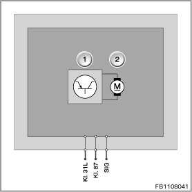
Index |
Explanation |
Index |
Explanation |
|---|---|---|---|
1 |
Electronic evaluation unit |
2 |
Coolant pump drive |
Pin assignments
Pin |
Explanation |
|---|---|
Kl. 31L |
Load ground |
Kl. 87 |
Battery voltage, terminal 15 on |
SIG |
Activation line for turbocharger coolant pump |
Characteristic curve and target values
There is no speed control for the turbocharger coolant pump (despite pulse width modulation configuration). The turbocharger coolant pump has an operating point of 2750 rpm.
Furthermore, the coolant pump is not suitable for operation with a continuous pulse. In addition, the coolant pump can be switched to low power output via the activation connection.
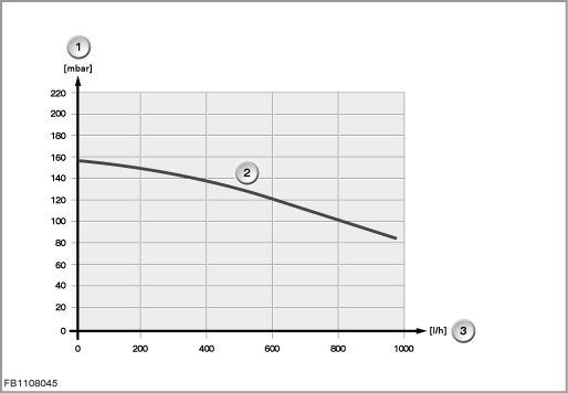
Index |
Explanation |
Index |
Explanation |
|---|---|---|---|
1 |
Differential pressure |
2 |
Characteristic curve at 12 V rated voltage |
3 |
Volumetric flow |
|
|
Observe the following target values for the turbocharger coolant pump:
Variable |
Value |
|---|---|
Speed (operating point) |
2750 rpm |
Supply rate (nominal operation) |
800 l/h |
Voltage range (full power output) |
9 to 16 V |
Maximum current consumption in normal operating mode |
1.2 A to 1.4 A |
Temperature range of coolant temperature |
-40 to 135 °C |
Temperature range |
-40 to 140 °C |
Diagnosis instructions
Failure of the component
If the turbocharger coolant pump fails, the following behaviour is to be expected:
- Fault memory entry in the engine control module
- Emergency operation with substitute value
General information
Diagnosis is started at ignition on.
No liability can be accepted for printing or other faults. Subject to changes of a technical nature