Headrest adjustment drive for driver's and/or passenger's side, rear
Headrest adjustment drive for driver's and/or passenger's side, rear
The button for the headrest adjustment in the rear can be used to move the back seat on the driver's and/or passenger's side electrically in the desired direction.
Drives for the headrest adjustment are installed in the rear seats on both the driver's side and passenger's side.
The memory function can be used to store and call up various seat positions.
The signals delivered by the Hall sensors to the drives are stored in the seat module to specify the position.
Functional description
The headrest adjustment drive for the driver's and/or passenger's side, rear comprises the following components:
- Adjustment motor
- Hall sensor for memory function
The seat module on the driver's side, rear (SMFAH) and/or passenger's side, rear (SMBFH) evaluates the button signal. Depending on the request, the seat module activates the drive for the headrest adjustment.
The adjusting path is registered by the Hall sensor in the adjustment motor and processed in the seat module. The position value of the mechanical limits stops is detected and stored as end stop the first time it is detected. For subsequent adjustments, the seat stops before this position is reached (soft stop). This prevents sustained mechanical tension in the seat mechanism.
The soft stop can be bypassed by pressing the button for headrest adjustment once again immediately afterwards.
For activation of the adjustment motor, integrated measurement of the control currents takes place in the seat module. This measurement ensures fault recognition (e.g. excess current, short circuit or blocking). If certain threshold values are exceeded or undershot, the power supply to the adjustment motor is switched off.
The seat module has its own overheating protection to prevent the adjustment motor from overheating. The heating of the adjustment motor is calculated continuously on the basis of the operation time (running time and off-load phase) by means of a thermal model in the seat module. As of a certain temperature threshold, the seat module switches off the adjustment motor.
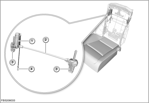
Index |
Explanation |
Index |
Explanation |
|---|---|---|---|
1 |
Adjustment motor |
2 |
Spindle |
3 |
Transmission |
4 |
4-pin plug-in connection |
Structure and inner circuit
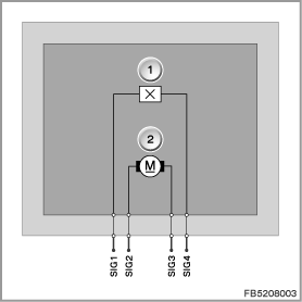
The headrest adjustment drive for the driver's and/or passenger's side, rear is a DC motor. The seat module controls the drive as of terminal 30B ON.
Index |
Explanation |
Index |
Explanation |
|---|---|---|---|
1 |
Hall-effect sensor |
2 |
Adjustment motor |
Pin assignments
Pin |
Explanation |
|---|---|
SIG1 |
Signal line from Hall sensor |
SIG2 |
Activation of the adjustment motor |
SIG3 |
Earth connection (terminal 31, load earth) of the adjustment motor |
SIG4 |
Activation of the Hall sensor |
Target values
Comply with the following target values for the headrest adjustment drive for the driver's and/or passenger's side, rear:
Variable |
Value |
|---|---|
Voltage range |
9 to 16 V |
Current consumption (for seat adjustment) |
6 A |
Temperature range |
-40 to 85 °C |
Diagnosis instructions
Failure of the component
If the headrest adjustment drive for the driver's and/or passenger's side, rear fails, the following behaviour is to be expected:
- Fault memory entry in the seat module for the driver's side, rear (SMFAH) and/or seat module for the passenger's side, rear (SMBFH)
General information
Information on seat calibration, see functional description ”Seat calibration”.
No liability can be accepted for printing or other faults. Subject to changes of a technical nature