Electric fan
Electric fan
The power output of the electric fan depends on the version: 850 Watts, hot country 1000 Watts. The electric fan is positioned behind the radiator. The engine management system activates the electric fan.
New is that the power supply is provided through terminal 30 via a relay from the engine management system. This electric fan cutoff relay is located in the luggage compartment beside the battery.
Functional description
The electric fan is controlled by the engine control module via a pulse-width-modulated signal (evaluation by electronic circuitry in the fan). The engine control module uses a pulse-width modulated signal (7 to 93 %) to control the various speeds of the radiator fan. Pulse duty factors less than 7 % and greater than 93 % do not trigger activation; they are used for fault detection. The speed of the radiator fan is dependent on the coolant temperature at the radiator outlet (radiator) and the pressure in the air-conditioning system. When the car's road speed increases, the speed of the radiator fan decreases.
For the after-run of the electric fan, the engine management system lowers the frequency to 10 Hz. The pulse duty factor is used to select the time (maximum 11 minutes) and the fan speed.
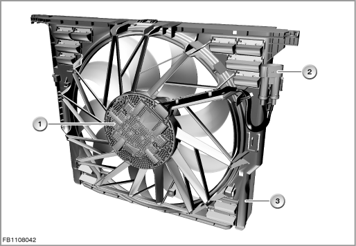
Index |
Explanation |
Index |
Explanation |
|---|---|---|---|
1 |
Drive for electric fan |
2 |
4-pin plug-in connection |
3 |
Fan cowl |
|
|
Structure and inner circuit
The drive of the electric fan is a brushless motor.
The electric fan has its own electronic evaluation unit and the speed is controlled by a pulse-width modulated signal. The pulse duty factor in the normal operating mode (100 Hz) is converted into a speed signal.
- 7 % pulse duty factor: Standby mode (electronic evaluation unit is kept awake)
- 11 % pulse duty factor: Minimum fan speed (33 % of the rated speed)
- 93 % pulse duty factor: Maximum fan speed
- 97 % pulse duty factor: Command for self-diagnosis of the electronic evaluation unit
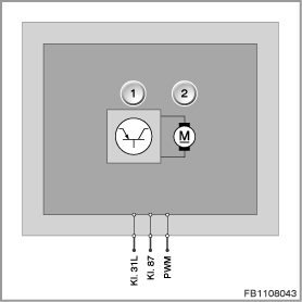
Index |
Explanation |
Index |
Explanation |
|---|---|---|---|
1 |
Electronic evaluation unit |
2 |
Drive for electric fan |
Pin assignments
Pin |
Explanation |
|---|---|
Kl. 31L |
Load ground |
Kl. 87 |
Battery voltage terminal 30 via cutoff relay for radiator fan |
PWM |
Pulse-width modulated signal |
Characteristic curve and target values
The permitted operating temperature lies between -20 °C and 120 °C. The static pressure lies between 0 and 0.8 bar.
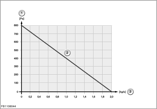
Example: Characteristic curve depending on the blower output
Index |
Explanation |
Index |
Explanation |
|---|---|---|---|
1 |
Static pressure |
2 |
Characteristic curves for flow rate |
3 |
Volumetric flow |
|
|
Observe the following target values for the electric fan:
Variable |
Value |
|---|---|
Voltage range |
8 to 17 Volts |
Rated speed |
2400 rpm |
Power output |
850 or 1000 Watt |
Maximum current consumption |
70 A ± 3 A |
Temperature range |
-40 to 120 °C |
Diagnosis instructions
Failure of the component
If the electric fan fails, the following behaviour is to be expected:
- Fault memory entry in the engine control module
- Power reduction (if engine overheated)
- Check Control message in the instrument cluster
- Damage to thermally critical components in the car front end after stopping the engine (post-heating of the engine)
General information
The electronic evaluation unit runs an internal diagnosis for critical states. If a fault is detected, operation is maintained as far as possible.
If activation by pulse width modulation fails, the electric fan is activated with a fixed pulse duty factor (emergency operation).
No liability can be accepted for printing or other faults. Subject to changes of a technical nature