Throttle-valve actuator
Throttle-valve actuator
The throttle-valve actuator is secured to the intake air collector.
A throttle valve is necessary for all diesel engines equipped with a particle filter system. The throttle valve chokes the intake air to ensure that the necessary increased exhaust-gas temperatures required for regeneration of the particulate filter are reached.
The throttle valve is closed while the engine is being turned off. This reduces engine shuddering during the shutdown operation.
Another function preventing the engine from overrevving. If the Digital Diesel Electronics (DDE) detect high revving without the fuel injection rate being increased, the throttle valve is closed to limit the engine speed.
Functional description
The throttle-valve actuator is electrically opened or closed by the DDE control module. To ensure optimized control of the throttle valve, the exact position must be continuously detected. To achieve this, the throttle-valve position is monitored in the throttle-valve actuator by the non-contact throttle-valve sensor.
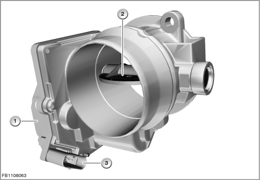
Index |
Explanation |
Index |
Explanation |
|---|---|---|---|
1 |
Throttle-valve actuator |
2 |
Throttle valve |
3 |
5-pin plug-in connection |
|
|
When no current is applied, the throttle valve is opened by spring force in the throttle-valve actuator.
Structure and inner circuit
The actuator motor for the throttle-valve adjustment is a DC motor.
The throttle-valve sensor is a Hall sensor. The Hall sensor determines the revolutions of the actuator motor. This is used to calculate the position of the throttle valve.
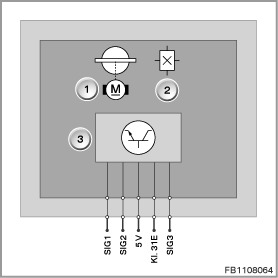
Index |
Explanation |
Index |
Explanation |
|---|---|---|---|
1 |
Throttle-valve actuator with throttle valve |
2 |
Hall-effect sensor |
3 |
Electronic module with electronic evaluation unit |
|
|
Pin assignments
Pin |
Explanation |
|---|---|
SIG1 |
Activation of throttle-valve actuator, plus |
SIG2 |
Activation of throttle-valve actuator, minus |
5 V |
Power supply for throttle-valve sensor |
Kl. 31E |
Throttle-valve sensor ground |
SIG3 |
Throttle-valve sensor signal |
Signal path and target values
The throttle-valve sensor is supplied with 5 Volts and ground by the DDE.
A bridge circuit (H bridge) is used to activate the actuator motor. This permits activation of the actuator motor in the opposite direction. The bridge circuit is monitored for diagnosis.
H bridge refers to an electrical gearshift where 5 shift elements are interconnected in the shape of the upper case letter H.
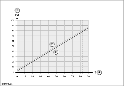
Index |
Explanation |
Index |
Explanation |
|---|---|---|---|
1 |
Throttle-valve position in % |
2 |
Maximum characteristic curve |
3 |
Minimum characteristic curve |
4 |
Throttle-valve opening angle in degrees |
Observe the following target values for the throttle-valve actuator:
Variable |
Value |
|---|---|
Power supply of actuator motor |
12 Volts |
Activation frequency for actuator motor |
1300 Hz |
Blocking current for actuator motor |
4 A |
Power supply for throttle-valve sensor |
4.5 to 5.5 V |
Current consumption of throttle-valve sensor |
10 mA |
Temperature range of throttle-valve sensor and actuator motor |
-40 °C to 140 °C |
Diagnosis instructions
Failure of the component
If the throttle-valve sensor fails, the following behaviour is to be expected:
- Fault memory entry in the engine control module
- Emergency operation with substitute value (limited engine torque)
- Check Control message
If the actuator motor fails, the following behaviour is to be expected:
- Fault memory entry in the engine control module
- Mechanical emergency air position of the throttle valve
- Check Control message
No liability can be accepted for printing or other faults. Subject to changes of a technical nature