Blower output stage
Blower output stage
The fan output stage is located directly at the fan motor. The fan output stage controls the voltage of the fan motor.
Functional description
At the fan output stage, the control module of the integrated automatic heating / air-conditioning system (IHKA control module) specifies the voltage for the fan motor. The specified voltage is output by the IHKA control module as a signal on the LIN bus.
Depending on this control signal, the fan motor is activated by the fan output stage.
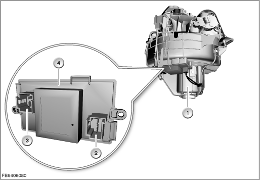
Index |
Explanation |
Index |
Explanation |
|---|---|---|---|
1 |
Fan of the climate control |
2 |
2-pin plug connection (connection to fan motor) |
3 |
4-pin plug connection (connection to the wiring harness) |
4 |
Blower output stage |
There is a temperature sensor on the fan output stage circuit board. At a temperature between 65 °C and 80 °C, within the framework of overheating protection, the output power of the fan output stage is reduced, leading to reduced fan output.
Structure and inner circuit
The fan output stage is supplied with voltage via terminal 30 by the junction box. The fan output stage is connected by 2 plug connections with the wiring harness and fan motor.
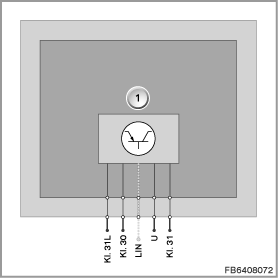
Index |
Explanation |
Index |
Explanation |
|---|---|---|---|
1 |
Blower output stage |
|
|
Assignment of pins (connection to wiring harness, 4-pin)
Pin |
Explanation |
|---|---|
Terminal 31L |
Terminal 31, load ground |
Terminal 30 |
Terminal 30, power supply |
LIN |
LIN bus |
1 pin not used. |
|
Assignment of pins (connection to fan motor, 2-pin)
Pin |
Explanation |
|---|---|
Terminal 31 |
Terminal 31, earth connection for fan motor |
U |
Power supply to fan motor |
Target values
Observe the following target values for the fan output stage:
Variable |
Value |
|---|---|
Voltage range |
9 to 16 V |
Maximum current consumption |
30.5 ± 1.5 A |
Temperature range |
-40 to 85 °C |
Diagnosis instructions
Failure of the component
If the fan output stage fails, the following behaviour is to be expected:
- Fault memory entry in the IHKA control module
- Fan inoperative
General information
The fan output stage has diagnostic capability. The corresponding diagnosis information is transferred across the LIN bus to the IHKA control module and evaluated there.
No liability can be accepted for printing or other faults. Subject to changes of a technical nature