Brake-light switch
Brake-light switch
Two Hall sensors as switches are built into the brake-light switch: The brake-light switch and the stop lamp test switch (duplicated as a safety measure). The signals indicate whether the brake pedal has been pressed. The data interchange is digital.
Functional description
The brake-light switch has no moving parts and works as a non-contact switch. A change in the switching state is achieved by removing or applying a ferromagnetic trigger element to the brake pedal.
Switching state with brake not activated:
Brake-light switch output conductive and stop lamp test switch output blocks.
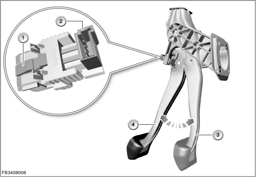
Index |
Explanation |
Index |
Explanation |
|---|---|---|---|
1 |
Brake-light switch |
2 |
4-pin plug-in connection |
3 |
Brake pedal pressed |
4 |
Brake pedal not pressed |
The two redundant signals from the brake-light switch are read in by the Car Access System (CAS). The CAS forwards the signals on the bus system, e.g. for the engine management system.
The signals from the brake-light switch are hard-wired and branched off for the following systems:
- Footwell module (FRM) for backup lamp
- Dynamic Stability Control (DSC) for brake intervention
Structure and inner circuit
The Hall IC and the magnet are firmly positioned in the switch housing. The brake pedal does not have to provide any restoring force for the brake-light switch.
The brake-light switch is supplied with voltage by the Car Access System (CAS) (terminal 30B).
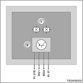
Index |
Explanation |
Index |
Explanation |
|---|---|---|---|
1 |
Hall sensors |
2 |
Electronic module |
Pin assignments
Pin |
Explanation |
|---|---|
Kl. 30B |
Terminal 30B, base operation |
SIG1 |
Ignition signal, terminal 1 |
SIG2 |
Ignition signal, terminal 1 |
Kl. 31 |
Ground connection |
Power supply and target values
Definition of terminal 30B base operation:
Energy power supply for components that are required during ”driver presence”. Switch on by driver action (e.g. locking, opening door).
Switch off following after-run time (depending on state, 1 to 30 min).
Observe the following target values for the brake-light switch:
Variable |
Value |
|---|---|
Voltage range |
6 to 16 V |
Current consumption in normal operating mode |
≤ 8 A |
Output resistance switch blocks |
1.5 m |
Temperature range |
-40 to 85 °C |
Diagnosis instructions
Failure of the component
If the brake-light switch fails, the following behaviour is to be expected:
- Fault memory entry in the Car Access System (CAS)
- Fault memory entry in the dynamic stability control (DSC)
- Fault memory entry in the footwell module (FRM)
- Fault memory entry in the engine management system due to the missing message on the bus system
No liability can be accepted for printing or other faults. Subject to changes of a technical nature