Parking brake button
Parking brake button
The parking brake button is located in the centre console behind the gear selector switch (GWS). The design of the parking brake button is based on the operations logic of a handbrake:
- Pull parking brake button upwards: the parking brake is activated
- Press parking brake button downwards: the parking brake is deactivated
An indicator lamp in the instrument cluster shows that the parking brake has been activated.
Functional description
Application is triggered by pulling the parking brake button.
With the engine running or vehicle rolling: The parking brake has a hydraulic effect on the disc brakes of the front and rear axle via the DSC.
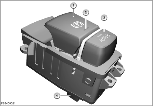
Index |
Explanation |
Index |
Explanation |
|---|---|---|---|
1 |
Parking brake button |
2 |
Function indicator lamps |
3 |
Automatic Hold button with function indicator lamp |
4 |
12-pin plug-in connection |
With the engine off and vehicle stationary:
The parking brake uses the electromechanical actuating unit to affect the drum brakes of the rear axle via Bowden cables. Driving off against the blocked brake pressure leads to another pressure increase and a Check Control message. Starting the engine causes a switch from electromechanical to hydraulic engagement.
Release is triggered by pressing the parking brake button. Here, the relevant active brake system opens. It is only possible to release the parking brake when the vehicle is stationary when the engine is on or off with the brake pedal pressed.
With the engine off (via bus signal ”status engine running”), there is a switch from hydraulic to electromechanical engagement.
Automatic hold function
The automatic hold function is activated using a button behind the parking brake button. When the function is selected, the vehicle is hydraulically braked from the first application of the brake by the DSC until it comes to a complete halt. When the engine is switched off, the parking brake assumes the holding function. Pressing the accelerator pedal releases the wheel brakes and the vehicle begins to move. The automation of the holding and release operation supports e.g. driving in city traffic or in traffic jams.
Structure and inner circuit
The centre console operating unit has a 12-pin plug connection.
The locating lights (terminal 58g) come from the footwell module (FRM). The junction box supplies the parking brake button with terminal 30.
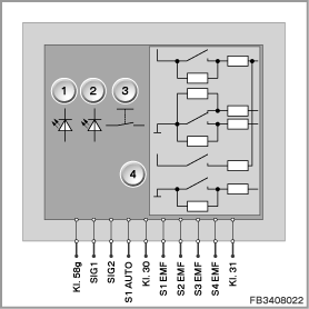
Index |
Explanation |
Index |
Explanation |
|---|---|---|---|
1 |
Function indicator lamp for parking brake button |
2 |
Function indicator lamp for Automatic Hold function |
3 |
Button for Automatic Hold function |
4 |
Parking brake button |
A button with 4 connections is required for vehicles with automatic transmissions. The evaluation of the button for engagement is redundant three ways and redundant in two ways for disengagement.
Pin assignments
Pin |
Explanation |
|---|---|
SIG1 |
Locating lights, terminal 58g |
SIG1 |
Function indicator lamp for parking brake button signal |
SIG2 |
Function indicator lamp for Automatic Hold function button signal |
S1 AUTO (Button) |
Automatic Hold function button signal |
Terminal 30 EMF |
Terminal 30 power supply |
S1 EMF |
Signal switch 1, parking brake |
S2 EMF |
Signal switch 2, parking brake |
S3 EMF |
Signal switch 3, parking brake |
S4 EMF |
Signal switch 4, parking brake |
Terminal 31 |
Terminal 31, ground |
Interfaces and target values
The buttons are electrically connected to different control modules:
- Button for Automatic Hold function to the Dynamic Stability Control (DSC)
- Parking brake button to the electromechanical parking brake (EMF)
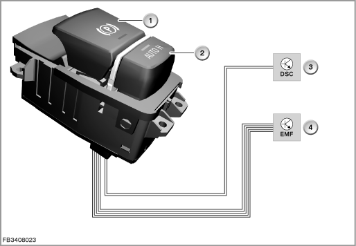
Index |
Explanation |
Index |
Explanation |
|---|---|---|---|
1 |
Parking brake button |
2 |
Button for Automatic Hold function |
3 |
DSC (Dynamic Stability Control) |
4 |
Electromechanical parking brake (EMF) |
Comply with the following target values for the parking brake button as well as the Automatic Hold function button:
Variable |
Value |
|---|---|
Force for resistance point of Automatic Hold function button |
5 N ±1 N |
Force for resistance point of parking brake button |
8 N ±1.2 N |
Path for Automatic Hold function button |
1.5 mm ±0.3 mm |
Path for parking brake button |
13° ±1.3° |
Power supply for switch contacts |
9 to 16 Volts |
Maximum current consumption of switch contacts |
1.5 mA |
Temperature range |
-40 to 140 °C |
Diagnosis instructions
Failure of the component
If the button for the Automatic Hold function fails, the following behaviour is to be expected:
- Fault memory entry in the DSC control module
- Check Control message in the instrument cluster
If the parking brake button fails, the following behaviour is to be expected:
- Fault memory entry in the EMF control module
- Check Control message in the instrument cluster
No liability can be accepted for printing or other faults. Subject to changes of a technical nature