Centre console operating unit
Centre console operating unit
The centre console operating unit is located to the left of the gear selector switch.
Depending on the options fitted, buttons for the following systems are integrated on the centre console operating unit:
- Dynamic Stability Control (series)
- Driving dynamics control via driving dynamics switch (series standard)
- Bumper camera
- Park distance control
Functional description
The following components are described for the centre console operating unit:
Driving dynamics switch
The driving dynamics switch is used to operate Driving Dynamics Control.
The new Driving Dynamics Control has the following innovations:
- All of the drive and driving dynamics systems installed in the vehicle are activated. The central control module for this is the Integrated Chassis Management (ICM).
- A choice of 4 programs is available:
- COMFORT
- Normal
- Sport
- SPORT+
- COMFORT
The selected program is shown in the instrument cluster.
Individual settings can be made on the Central Information Display (CID) at 'Options'.
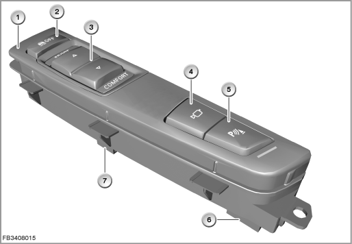
Index |
Explanation |
Index |
Explanation |
|---|---|---|---|
1 |
Centre console operating unit |
2 |
DTC button |
3 |
Driving dynamics switch |
4 |
Button for bumper camera |
5 |
PDC button with function indicator lamp as well as button for rear view camera |
6 |
4-pin plug-in connection |
7 |
6-pin plug-in connection |
|
|
The following systems are influenced by Driving Dynamics Control:
- Accelerator pedal module
- Automatic transmission
- Steering
- Vertical dynamics management (VDM) via shock absorbers as well as active roll stabilization
- Dynamic Stability Control
DTC button = DSC OFF
A new legal regulation means that the DTC button bears the labeling ”OFF” as well as a symbol representing a skidding vehicle. The indicator lamp in the instrument cluster also bears this symbol (consult Owner's Manual).
The DTC button can be used to select 3 switching states:
- DTC button not pressed after terminal change: DSC in operation (default)
- Press DTC button briefly: DTC in operation (display TRACTION in the revolution counter)
- Press DTC button for longer period: DSC and ASC switched off, ABS and ABD-X on all wheel drive still active (display DSC OFF in the revolution counter)
Note! Pressing for too long creates a fault memory entry.
If the driving dynamics switch or DTC button are pressed for longer than 10 seconds, a fault is entered in the Integrated Chassis Management (ICM).
DSC goes into operation.
Bumper camera button
The pickup range of the cameras is a maximum of 100 metres. The images of both cameras are shown simultaneously on the Central Information Display (CID). The bumper cameras are switched on by pressing the button. The system is switched off at a driving speed of 15 km/h.
PDC button
The PDC button switches the parking aid on or off (see Owner's Manual).
PDC provides support for parking. Slow approaches to an object in front of or behind the vehicle are indicated by:
- Signal tones
- Visual display in the CID
Structure and inner circuit
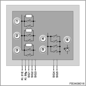
The centre console operating unit has 2 plug connections (6-pin and 4-pin).
The locating lights (terminal 58g) come from the footwell module (FRM).
Index |
Explanation |
Index |
Explanation |
|---|---|---|---|
1 |
DTC button |
2 |
SPORT driving dynamics switch |
3 |
COMFORT driving dynamics switch |
4 |
Button for bumper camera |
5 |
PDC button |
6 |
Function indicator lamp for PDC button (LED) |
Pin assignments
Pin |
Explanation |
|---|---|
Terminal 31 |
Ground, terminal 31 |
Terminal 58g |
Locating lights, terminal 58g |
SIG1 |
DTC button signal |
SIG2 |
SPORT driving dynamics switch signal |
SIG3 |
COMFORT driving dynamics switch signal |
Pin |
Explanation |
|---|---|
SIG4 |
Signal for bumper camera button and PDC button |
SIG5 |
Function indicator lamp for PDC (LED) |
Interfaces and target values
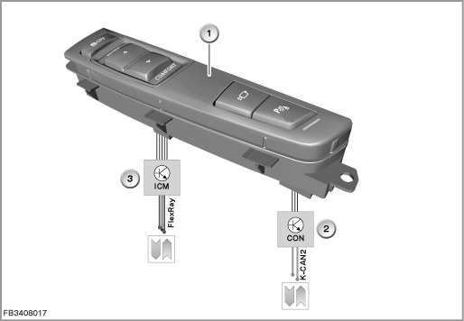
The button in the centre console operating unit are electrically connected to different control modules:
- Driving dynamics switch and DTC button to the Integrated Chassis Management (ICM)
- Bumper camera button and PDC button to the controller (CON)
Index |
Explanation |
Index |
Explanation |
|---|---|---|---|
1 |
Centre console operating unit |
2 |
Controller (CON) |
3 |
Integrated Chassis Management (ICM) |
|
|
Observe the following target values for the centre console operating unit:
Variable |
Value |
|---|---|
Cycles of switch contacts |
50.000 |
Power supply for switch contacts |
9 to 16 Volts |
Maximum current consumption of switch contacts |
1.5 mA |
Maximum contact resistance of switch contacts |
150 |
Temperature range |
-40 to 140 °C |
Diagnosis instructions
Failure of the component
In principle, only the individual buttons on the centre console operating unit can fail.
The ICM monitors the connected buttons as follows:
- Open circuit
- Short circuit to ground
- Continuous operation
The controller does not monitor the connected buttons.
If a button is pressed for a sustained period (e.g. by a handbag), a fault is entered in the fault memory of the corresponding control module.
A function check of the buttons can be run using the BMW diagnosis system.
No liability can be accepted for printing or other faults. Subject to changes of a technical nature