A/C compressor
A/C compressor
The A/C compressor driven by the engine by means of a belt drive. The A/C compressor is switched on and off via a magnetic clutch.
Functional description
Stepless power control is possible in the A/C compressor. Within the A/C compressor, the delivery volume and thus the pressure in the refrigerant circuit is generated by pistons. The piston stroke is controlled by a swash plate.
With the help of this movement, the swash plate regulates:
- Minimum working volume (less than 3 %)
The electrical control valve is open without current. In this position, the compressor output is lowered to almost 0 % to reduce fuel consumption.
With the air conditioning system switched on, the minimum compressor output lies between 0 % and 3 %; this is implemented to maintain the inner lubrication.
Furthermore, pressure build-up is enabled even if liquefied refrigerant has collected in the compressor (due to physical factors). - Maximum displacement (100 %)
- Control range (0 % to 100 %)
The electric control valve on the A/C compressor influences the balance of forces on the swash plate and thus the adjustment of the displacement. The junction box electronics (JBE) control the control valve with a clocked voltage. The IHKA control module prompts the actuation.
To reduce the load, only the currently required cooling output is generated.
The control and switching criteria for this are:
- A/C compressor speed (engine speed)
- Load torque of the A/C compressor (CAN message from the IHKA control module to the engine control module)
- Torque limitation (CAN message from engine control module to IHKA control module)
Restriction of A/C compressor load torque at kick-down position or if coolant temperature is too high - Limitation of refrigerant pressure
- Outside temperature
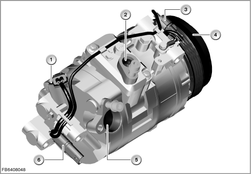
Index |
Explanation |
Index |
Explanation |
|---|---|---|---|
1 |
Electrical control valve with 2-pin plug-in connection |
2 |
Connection for refrigerant line (pressure line) |
3 |
1-pin plug-in connection from the magnetic clutch |
4 |
Magnetic clutch and belt pulley |
5 |
Connection for refrigerant line (intake line) |
6 |
3-pin plug-in connection (connection to vehicle network) |
Structure and inner circuit
The A/C compressor is connected to the vehicle network by means of 2 plug-in connections.
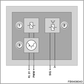
Index |
Explanation |
Index |
Explanation |
|---|---|---|---|
1 |
Electric control valve |
2 |
Magnetic clutch |
3 |
Electronic module |
|
|
Assignment of pins for electrical control valve
Pin |
Explanation |
|---|---|
Kl. 31 |
Terminal 31 |
PWM |
Pulse-width modulated signal (PWM signal) |
Assignment of pins for magnetic clutch
Pin |
Explanation |
|---|---|
SIG |
Signal line |
Assignment of pins for A/C compressor (connection to the vehicle network)
Pin |
Explanation |
|---|---|
Kl. 31 |
Terminal 31 |
PWM |
Pulse-width modulated signal (PWM signal) for the electrical control valve |
SIG |
Signal wire for the magnetic clutch |
Target values
Observe the following target values for the magnetic clutch:
Variable |
Value |
|---|---|
Power supply |
12 V |
Voltage range |
7.5 to 16.5 V |
Maximum torque |
36 Nm |
Power consumption (after 15 minutes' operation at 20 °C and U = 12 Volts) |
35 - 42 W |
Current consumption (at 20 °C and U = 12 Volts) |
2.8 to 3.2 A |
Observe the following target values for the electric control valve:
Variable |
Value |
|---|---|
Power supply |
12 V |
Voltage range |
9 to 16.5 V |
PWM signal |
400 ± 10 Hz |
Control current, A/C compressor ”ON” |
0.26 to 0.92 A |
Observe the following target values for the A/C compressor:
Variable |
Value |
|---|---|
Displacement |
170 cm3 |
Number of cylinders |
7 |
Opening pressure for safety valve on the A/C compressor |
40 ± 4 bar |
Diagnosis instructions
Protective function if A/C compressor is blocked
A thermal fuse in the casting of the coil in the magnetic clutch is a protection function if the A/C compressor blocks.
If the thermal load on the magnetic clutch reaches a certain temperature (189 °C ± 10 K), the thermal fuse trips. This interrupts the power supply to the magnetic clutch.
The magnetic clutch is open without current. This interrupts the transmission of torque from the pulley to the driver, which is linked to the shaft of the A/C compressor.
If the thermal fuse trips, the A/C compressor must be replaced in Service.
Reason: The thermal fuse is not reversible and cannot be replaced as an individual component.
Failure of the component:
If the magnetic clutch (elec. activation) fails, the following behaviour is to be expected:
- Fault memory entry in the junction box electronics (JBE)
- The magnetic clutch is open without current. This means the A/C compressor is not driven. A/C operation not possible.
If the electric control valve (elec. activation) fails, the following behaviour is to be expected:
- Fault memory entry in the junction box electronics (JBE)
- The electrical control valve is open without current. The result of this is a minimum working volume.
No liability can be accepted for printing or other faults. Subject to changes of a technical nature