ECO valve
ECO valve
The ECO valve is attached to the power-steering pump.
ECO stands for: Electronically Controlled Orifice.
The power-steering pump is regulated in accordance with demand by the ECO valve. The ECO valve regulates the volumetric flow of the hydraulic fluid and thus the hydraulic power output.
Depending on the options fitted (active steering, Dynamic Drive), a tandem pump can be installed.
Functional description
Modern rack and pinion power steering creates high wheel-angle rates (wheel is turned more quickly). The power available in the hydraulic system must be correspondingly higher in order to obtain these faster wheel-angle rates. A conventional vane-cell pump of adequate size and capacity would result in unacceptable power losses. Fuel consumption, too, would be increased to an unnecessary extent. This situation can be alleviated with the aid of a variable-output power-steering pump. The ECO valve in the power-steering pump regulates the volumetric flow depending on the requirement and lowers the backpressure in the hydraulic system.
In this way, the ECO valve affects the power consumption of the power-steering pump. The fuel consumption and carbon dioxide emissions (CO2) for the vehicle's engine are reduced.
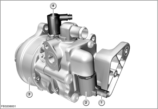
Index |
Explanation |
Index |
Explanation |
|---|---|---|---|
1 |
2-pin plug-in connection |
2 |
ECO valve (power-steering pump) |
3 |
Tandem pump (power-steering pump and active roll stabilization) |
4 |
Drainage coil valve |
When the ECO valve closes, the static pressure in the hydraulic system decreases. The hydraulic fluid delivered by the pump returns through the open pressure-control valve in the bypass to the expansion tank. This means the power-steering pump does not have to pump against the hydraulic resistance in the hydraulic system (cooler of the power-steering pump, hydraulic hoses). The power-steering pump requires less power. When the ECO valve opens, the pressure in the hydraulic system increases. The pressure control valve closes the return to the expansion tank in the short circuit. The pressure limiting valve limits the system pressure to 135 bar.
Structure and inner circuit
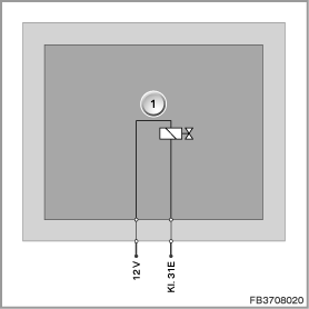
The ECO valve is connected to the Integrated Chassis Management (ICM) by means of a 2-pin plug-in connection.
The ECO valve is a solenoid valve. The ICM control module supplies the ECO valve with voltage and ground.
Index |
Explanation |
Index |
Explanation |
|---|---|---|---|
1 |
ECO valve |
|
|
Pin assignments
Pin |
Explanation |
|---|---|
12 V |
Power supply for ECO valve |
Terminal 31E |
Terminal 31, electronics earth for ECO valve |
Characteristic curve and target values for power-steering pump
The power-steering pump is operated with pentosin.
The deployment of 2 different ECO valves is possible:
- Open without current (0 Ampere = maximum volumetric flow, 1 Ampere = minimum volumetric flow)
- Closed without current (1 Ampere = maximum volumetric flow, 0 Ampere = minimum volumetric flow)
Index |
Explanation |
Index |
Explanation |
|---|---|---|---|
1 |
Regulated delivery volume |
2 |
1 Ampere |
3 |
0 Ampere |
4 |
Pump speed |
Observe the following target values for the ECO valve:
Variable |
Value |
|---|---|
Voltage range |
8 to 16 V |
Resistance |
4.5 to 8.2 |
Current consumption |
approx. 1 A |
Pulse width modulation |
250 Hz |
Temperature range |
-40 °C to 135 °C |
Diagnosis instructions
Failure of the component
If the ECO valve fails, the following behaviour is to be expected:
- Fault memory entry in the ICM control module
No liability can be accepted for printing or other faults. Subject to changes of a technical nature