Servotronic valve
Servotronic valve
The Servotronic valve is attached to the rack and pinion power steering.
The Servotronic controls the degree of assistance provided by the hydraulic steering as a function of the vehicle's speed. The flow of hydraulic fluid is restricted to a greater or lesser extent depending on how the Servotronic valve is actuated. Restriction of the flow depends on the current actuating the Servotronic valve.
Functional description
The signals and messages required for the Servotronic are as follows:
- Road speed from the DSC control module via the bus system
- Status of the engine from the engine control module via bus system
- Terminal status from the CAS control module via bus system
The Servotronic valve is only activated at terminal 15 On and with the engine running. When the speed signal is present, the setting of the nominal current is taken from the characteristic curve.
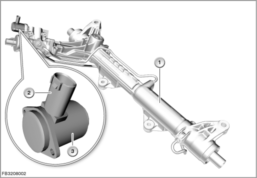
Index |
Explanation |
Index |
Explanation |
|---|---|---|---|
1 |
Rack and pinion power-steering |
2 |
2-pin plug-in connection |
3 |
Servotronic valve |
|
|
In the event of a short circuit to positive, the entire on-board network voltage is applied to the Servotronic valve. This means that the Servotronic valve is fully actuated. The power-assisted steering is at its maximum.
Structure and inner circuit
The Servotronic valve is connected to the Integrated Chassis Management (ICM) by means of a 2-pin plug-in connection.
The Servotronic valve is a solenoid valve. The ICM control module supplies the Servotronic valve with voltage and ground.
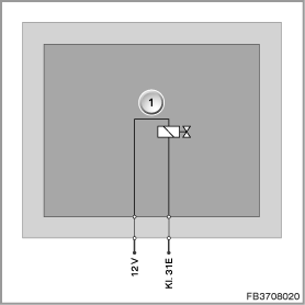
Index |
Explanation |
Index |
Explanation |
|---|---|---|---|
1 |
Servotronic valve |
|
|
Pin assignments
Pin |
Explanation |
|---|---|
12 V |
Power supply for Servotronic valve |
Terminal 31E |
Terminal 31, electronics earth for Servotronic valve |
Characteristic curve and target values
The Servotronic determines most of the steering momentum that driver has to apply. The Servotronic is mainly determined via the driving speed.
- Lower road speed range (urban driving, parking) = low steering momentum
- High road speed range (dual carriageway, motorway) = high steering momentum
Applying current to the Servotronic valve sets the corresponding characteristic curve.

Index |
Explanation |
Index |
Explanation |
|---|---|---|---|
1 |
Differential pressure between working cylinders |
2 |
Steering momentum |
Observe the following target values for the Servotronic valve:
Variable |
Value |
|---|---|
Maximum operating pressure |
127 +8 bar |
Operating range |
5 to 13 l/min |
Voltage range |
8 to 16 V |
Current consumption |
approx. 1 A |
Temperature range |
-40 °C to 135 °C |
Diagnosis instructions
Failure of the component
If the Servotronic fails, the following behaviour is to be expected:
- Fault memory entry in the ICM control module
No liability can be accepted for printing or other faults. Subject to changes of a technical nature