Air supply system
Air supply system
The ride-height control works by feeding or extracting air into or out of the air springs of the rear axle. The rear height-level sensors provide the EHC control module (EHC = electronic ride-height control) with information on the heights of the left and right sides of the vehicle. If the ride height is outside defined tolerances, the system will automatically activate the air supply unit to regulate to the specified level.
It should be borne in mind here that different tolerances apply depending on the vehicle status. Without engine operation, very broad limits (approx. -60 mm) apply to upward regulation. The tighter limits (±10 mm) are only active when the engine is running.
Changes to the load mainly take place when the vehicle is at a standstill, before or after a journey. In order to load the vehicle, the doors or luggage compartment / rear hatch have to be opened. The system is activated when a door or the luggage compartment lid is opened. The system switches off 20 minutes after the driver leaves the vehicle at the latest.
Important Perform ride-height calibration
Following part replacement (EHC control module, height-level sensors, or assembly work on parts of the rear axle), a ride-height calibration must be carried out. A service function is available on the BMW diagnosis system:
Chassis > Electronic ride-height control > Ride-height calibration
Functional description
The functions of the air supply unit are implemented by activating the compressor and the solenoid valves. The EHC control module controls the functions. The air supply unit contains the following components:
- Electric motor for drive of the compressor
- Compressor with air drier
- Drain valve with pressure limitation function
- Solenoid valve block with 2 solenoid valves (2/2-way valves)
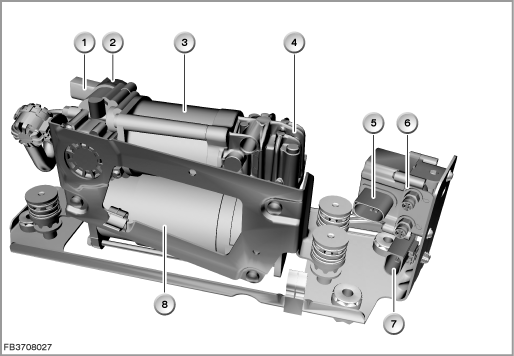
Index |
Explanation |
Index |
Explanation |
|---|---|---|---|
1 |
2-pin plug-in connection for drain valve |
2 |
Drain valve |
3 |
Air drier |
4 |
3-pin plug-in connection for solenoid valve block |
5 |
Solenoid valve block |
6 |
2-pin plug-in connection for electric motor |
7 |
Electric motor |
|
|
The following components of the air supply unit are described:
Compressor
The compressor is driven by an electric motor. Power is supplied to the electric motor via a relay. The relay is activated by the EHC control module until the specified nominal height is reached. The compressor temperature is monitored by a time model (stored in the EHC control module). If the maximum run time of the compressor is exceeded, other adjustments are suppressed. Once the value drops below the threshold value for switching on again, adjustments can be made again.
Air drier
The air taken in by the compressor passes over a water-absorbing filter in the air drier. This withdraws moisture from the air. As long as the air is more moist than the filter, the filter absorbs the moisture. On flowing back, the air is drier than the filter. This returns the moisture to the air and is escapes.
Drain valve
The drain valve is activated by the EHC control module. The air escapes from the solenoid valve block via the drain valve through the air drier.
The pressure limitation function of the drain valve limits the pressure in the air supply unit to approx. 20 bar:
Solenoid valve block
The solenoid valve block maintains the pressure in the air springs. During ride-height regulation, the solenoid valve enables the air to flow into or out of the air springs. The EHC control module activates the solenoid valves. Both sides of the car are regulated individually by the EHC control module.
Structure and inner circuit
The electric motor is supplied with voltage (terminal 30) via by the rear distribution box via the compressor relay.
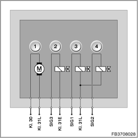
Index |
Explanation |
Index |
Explanation |
|---|---|---|---|
1 |
Electric motor |
2 |
Drain valve |
3 |
Solenoid valve for air springs, left |
4 |
Solenoid valve for air springs, right |
Pin assignments
Pin |
Explanation |
|---|---|
Terminal 30 |
Terminal 30, power supply for electric motor |
Terminal 31L |
Terminal 31L, load earth |
PWM |
Activation of drain valve |
Terminal 31E |
Terminal 31, electronics ground |
SIG1 |
Activation of solenoid valve for air springs, left |
Terminal 31L |
Terminal 31L, load earth |
SIG2 |
Activation of solenoid valve for air springs, right |
Power output diagram for compressor and target values
The air volume delivered by the compressor depends on the back pressure in the system.
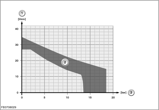
Index |
Explanation |
Index |
Explanation |
|---|---|---|---|
1 |
Volumetric flow |
2 |
Power output diagram for compressor |
3 |
Generated pressure |
|
|
Observe the following target values for the components of the air supply unit:
Variable |
Value |
|---|---|
Power supply for compressor |
9 to 16 V |
Maximum current consumption of compressor |
27 A |
Maximum current consumption of drain valve |
1.3 A |
Maximum current consumption of solenoid valve |
1.1 A |
Temperature range for air supply unit |
-40 to 80 °C |
Diagnosis instructions
Failure of the component
If one of the components of the air supply unit fails, the following behaviour is to be expected:
- Fault memory entry in the control module for electronic ride-height control (EHC)
- Check Control message in the instrument cluster
General information
On replacement of an air spring, a service function must be carried out with the BMW diagnosis system before and after:
- Before: Venting procedure
- After: Ventilation routine
No liability can be accepted for printing or other faults. Subject to changes of a technical nature