Valve block for lumbar support, driver and/or passenger
Valve block for lumbar support, driver and/or passenger
The lumbar support in the backrest consists of 2 inflatable lumbar cushions with a total of 4 valves in one valve block. The lumbar cushions partially overlap.
A pneumatic pump supplies the lumbar cushions with compressed air. Depending on the selected setting, the individual lumbar cushions are filled or emptied. This means that the lumbar support can vary its height and strength (adjustment of upper lumbar support and adjustment of lower lumbar support).
The lumbar support can be set as of terminal 30B ON. Buttons for the lumbar-support adjustment are installed in the switch block for the seat adjustment on the driver's side and in the switch block for the seat adjustment on the passenger's side. The button signals are transferred from the switch block across a LIN bus to the seat module on the driver's side (SMFA) and/or seat module on the passenger's side rear (SMBF). The seat module activates the pneumatic pump and the valve block.
The installation location of the valve block depends on the seat version and optional equipment fitted.
Functional description
Valve block for lumbar support in vehicles with active seat equipment
The valve technology used is not based on a solenoid valve rather on a wire made of shape memory alloy. As of a certain temperature, this wire changes its grid structure and contracts. The wire always attempts to reassume its original shape.
There is a valve with 2 wires for each lumbar cushion. One wire opens or closes the air duct for deflation. The other wire opens or closes the air duct for inflation. Without current, the valves are closed.
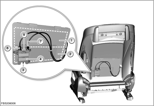
Index |
Explanation |
Index |
Explanation |
|---|---|---|---|
1 |
Lumbar cushion 1 |
2 |
Lumbar cushion 2 |
3 |
Connection for compressed air supply |
4 |
Valve block for lumbar support, driver and/or passenger |
5 |
6-pin plug-in connection |
6 |
Connection for the air duct to lumbar cushion 2 |
7 |
Connection for the air duct to lumbar cushion 1 |
|
|
Valve block for lumbar support in vehicles without active seat
The lumbar cushions are inflated or deflated via solenoid valves. Without current, the solenoid valves are closed.
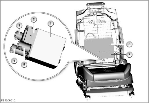
Index |
Explanation |
Index |
Explanation |
|---|---|---|---|
1 |
Valve block for lumbar support, driver and/or passenger |
2 |
6-pin plug-in connection |
3 |
Connection for the air duct to lumbar cushion 2 |
4 |
Connection for the air duct to lumbar cushion 1 |
5 |
Connection for compressed air supply |
6 |
Lumbar cushion 1 |
7 |
Lumbar cushion 2 |
|
|
Structure and inner circuit
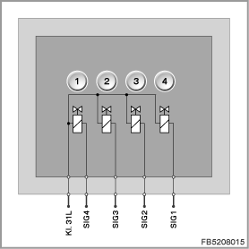
The valve block for the lumbar support for the driver and/or passenger is connected by means of a 6-pin plug connection to the driver seat module (SMFA) and/or passenger seat module (SMBF).
Index |
Explanation |
Index |
Explanation |
|---|---|---|---|
1 |
Inflation valve (wire made of shape memory alloy*) for lumbar cushion 1 |
2 |
Deflation valve (wire made of shape memory alloy*) for lumbar cushion 1 |
3 |
Inflation valve (wire made of shape memory alloy*) for lumbar cushion 2 |
4 |
Deflation valve (wire made of shape memory alloy*) for lumbar cushion 2 |
* only with active seat, otherwise solenoid valve |
|||
Pin assignments
Pin |
Explanation |
|---|---|
Terminal 31L |
Terminal 31, load ground |
SIG1 |
Inflate lumbar cushion 1 |
SIG2 |
Deflate lumbar cushion 1 |
SIG3 |
Inflate lumbar cushion 2 |
SIG4 |
Deflate lumbar cushion 2 |
1 pin not used. |
|
Target values
Comply with the following target values for the valve block of the lumbar support for the driver and/or passenger:
Variable |
Value |
|---|---|
Voltage range |
9 to 16 V |
Maximum current consumption at the valve |
300 mA |
Temperature range |
-40 to 85 °C |
Diagnosis instructions
Failure of the component
If the valve block of the lumbar support for the driver and/or passenger fails, the following behaviour is to be expected:
- Fault memory entry in the driver seat module (SMFA) or passenger seat module (SMBF)
No liability can be accepted for printing or other faults. Subject to changes of a technical nature