Injectors
Injectors
The injector sprays the fuel into the combustion chamber under high pressure. The injector opens the tip of the nozzle needle outwards and forms a ring gap that is only a few micrometres wide. The ring gap forms the high-precision fuel injection and ensures its even, cone-shaped spread.
Compared to activation via solenoid coils, the Piezo-electrical activation has the following advantages:
- Improved possibilities for multiple fuel injection due to rapid switching times with very short dead times.
This results in significant improvements with regard to pollutant emissions as well as fuel consumption.
Functional description
The outwardly opening injector enables high-precision fuel injection. Only this makes it possible to keep the injected fuel cone stable, also under the prevailing influences of pressure and temperature in the combustion chamber. This injector enables injection pressures of up to 200 bar and extremely fast opening of the nozzle needle. This makes it possible to inject fuel into the combustion chamber regardless of the operating cycles restricted by the valve opening times.
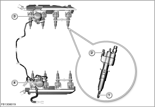
Index |
Explanation |
Index |
Explanation |
|---|---|---|---|
1 |
Injectors |
2 |
2-pin plug-in connection |
3 |
High-pressure pump, cylinders 1 to 4 |
4 |
High-pressure pump, cylinders 5 to 8 |
The volume of fuel required for the operating situation is injected by an injector into the combustion chamber. This volume can be influenced with three adjusting values:
- Rail pressure
- Injector nozzle opening duration
- Injector opening stroke
The nozzle opening duration and opening stroke are specified by the engine management system. The nozzle opening duration is controlled via the fuel injection signal (Ti signal). The opening stroke is controlled via the amount of energy in activation of the injector.
Structure and inner circuit
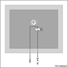
A piezo element is an electromechanical converter. The piezo element is a type of ceramic that converts electrical energy directly into mechanical energy (power/travel). The piezo element expands when voltage is applied. This creates the lift of the nozzle needle. To achieve a greater lift, a piezo element can be structured in a number of layers.
Index |
Explanation |
Index |
Explanation |
|---|---|---|---|
1 |
Injectors |
|
|
Pin assignments
Pin |
Explanation |
|---|---|
160 V |
Injector power supply (transformed upwards) |
Kl. 31E |
Electronics ground, injector activation |
Activation and target values
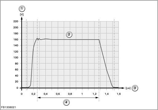
The engine management system is supplied with vehicle voltage. The engine management system contains a DC/DC converter across which the voltage is transformed upwards for activation of the injector. The injector is activated by the engine management system on the ground side.
Index |
Explanation |
Index |
Explanation |
|---|---|---|---|
1 |
High voltage |
2 |
Injection signal |
3 |
Time |
4 |
Fuel injection period |
Observe the following target values for the injector:
Variable |
Value |
|---|---|
Maximum power supply |
190 Volts |
System pressure |
5 to 20 MPa |
Nozzle opening duration, nozzle closing duration |
100 to 200 s |
Dynamic throughflow at 0.4 ms |
14.5 mg/stroke |
Temperature range |
-30 °C to 140 °C |
Diagnosis instructions
Failure of the component
If an injector fails, the following behaviour is to be expected:
- Fault memory entry in the engine control module
- Cylinder cutout
- The emissions warning lamp lights up in the instrument cluster
No liability can be accepted for printing or other faults. Subject to changes of a technical nature