Dual water valve
Dual water valve
The integrated automatic heating/air-conditioning system (IHKA) is a water-regulated heating and air conditioning system.
In the climate control, the air-mass flow is first cooled and dried at the evaporator (provided the air conditioner is switched on). Subsequently, the air-mass flow is heated at the heat exchanger for the heating system to the desired target values (left-right separation).
On the IHKA, a dual water valve is used for the left-right separation of the heating system heat exchanger. The dual water valve meters the coolant flow volume for the left and right heat exchanger for heating system in line with requirements. This determines the air temperature used for heating the vehicle interior.
Functional description
The dual water valve is electromagnetic. The dual water valve is activated by a pulse-width modulated signal (PWM signal) from the junction box electronics (JBE). The request comes from the IHKA control module.
The valve is opened and closed with a duty cycle specified by the electronics in line with requirements.
Without current, the dual water valve is open.
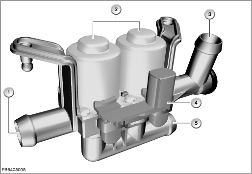
Index |
Explanation |
Index |
Explanation |
|---|---|---|---|
1 |
Left heating feed line (to the heat exchanger for heating system) |
2 |
Solenoid valves |
3 |
Right heating feed line (to the heat exchanger for heating system) |
4 |
3-pin plug-in connection |
5 |
Feed |
|
|
Structure and inner circuit
The dual water valve has 2 solenoid valves, 2 voltage-dependent resistors and a plug-in connection.
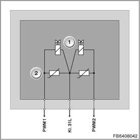
Index |
Explanation |
Index |
Explanation |
|---|---|---|---|
1 |
Solenoid valves |
2 |
Voltage-dependent resistors |
Pin assignments
Pin |
Explanation |
|---|---|
Kl. 31L |
Terminal 31, load ground |
PWM1 |
Pulse-width modulated signal (PWM signal) for solenoid valve in the left heating feed line |
PWM2 |
Pulse-width modulated signal (PWM signal) for solenoid valve in the right heating feed line |
Target values
Observe the following target values for the dual water valve:
Variable |
Value |
|---|---|
Power supply |
13 V |
Temperature range |
-40 to 120 °C |
Diagnosis instructions
After-run time: The dual water valve is still supplied with current after terminal 15N OFF for a certain time (value can be coded in the EEPROM).
Failure of the component:
If the dual water valve fails, the following behaviour is to be expected:
- Fault memory entry in the junction box electronics (JBE)
- Dual water valve remains open after failure:
Temperature control not possible; the temperature of the air-mass flow depends on the coolant temperature (air-mass flow cannot be cooled). - Dual water valve remains closed after failure:
Temperature control not possible; the air-mass flow cannot be heated.
No liability can be accepted for printing or other faults. Subject to changes of a technical nature