Setting of the NVE camera
Calibration of the NVE is possible using service function AS6654_NIVIF01!
After removing / installing the NVE camera, it must be mechanically calibrated. The mechanical setting as described below is only possible in the axial direction.
Required preliminary work:
Create access to the adjusting screw.
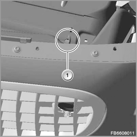
Number |
Definition |
1 |
Installation location of the adjusting screw |
Setup before calibration
The vehicle front must be parallel to the headlamp alignment device at a distance of 2 m. Align a suitable straight object, e.g. a spirit level, horizontally on the headlamp alignment device. Slowly adjust the NVE camera at the adjusting screw in an axial direction.
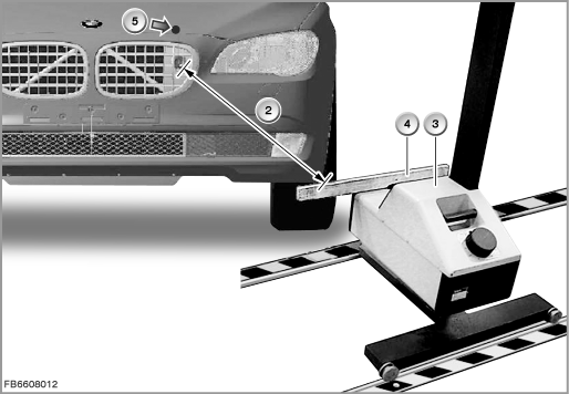
Number |
Definition |
2 |
The distance between the spirit level and the NVE camera |
3 |
Headlamp adjustment units |
4 |
Spirit level / straight object |
5 |
Installation location of the adjusting screw |
With the engine compartment lid opened, the 6 mm INBUS adjusting screw is accessible through an access hole in the air guide.
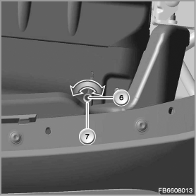
Number |
Definition |
6 |
Adjusting screw |
7 |
Access hole in the air guide |
Calibration of the NVE camera
The bottom illustration shows the CID image in the vehicle. If necessary, obtain assistance from a second person to align the NVE camera image. The yellow artificial line appears by means of a diagnosis job. The top edge must be aligned by means of the adjusting screw parallel to the artificial line in the CID.
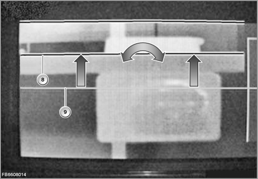
Number |
Definition |
8 |
Top edge |
9 |
Yellow artificial line |