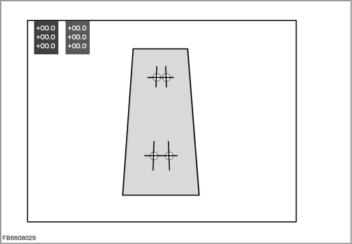
Calibration of the back-up camera
To calibrate the back-up camera, the lines shown in the picture must be brought into the right position on the target. The calibration requires a defined vehicle status.
On calibration, the full screen mode is activated automatically!
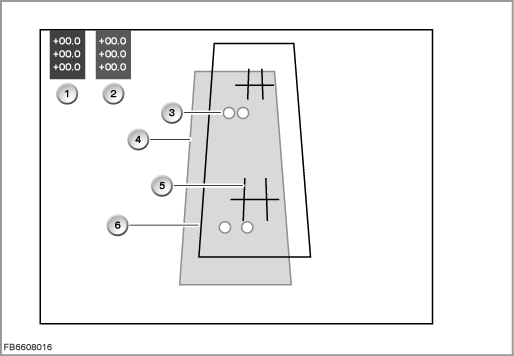
Number |
Definition |
1 |
Rotation values, colour red |
2 |
Shift values, colour blue |
3 |
Circles on the target |
4 |
Target |
5 |
Crosses on the overlay |
6 |
Overlay |
Here, the rotation and shift values are all set to zero. These will change with each alteration. Only the values that have been entered are displayed here. The values for rotation and shift read from the control module can deviate.
Securing the target
Secure the target to the rear axle as described in the repair instruction.
Positioning of the rear view camera
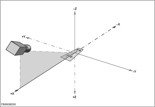
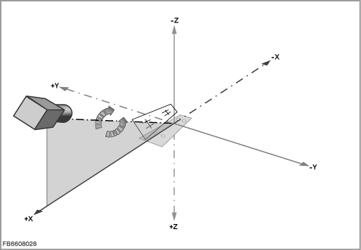
The positioning of the rear view camera and of the camera image in the co-ordinate system are displayed. The rear view camera is aligned in the direction of the x-axis.
Setting options
The rear view camera can be rotated and shifted. It can be shifted in the x, y or z direction. Rotating involves an angle change in x or z direction and around the centre of the camera image. The crosses on the overlay must be moved until they are in the centre of target circles.
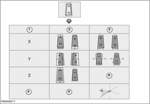
Number |
Definition |
1 |
Axis |
2 |
Shift |
3 |
Rotation |
4 |
Rotating around the centre of the camera image |
5 |
No possibility to make changes |
6 |
No possibility to make changes |
Correct the shift on the x-axis, y-axis and z-axis.
Shift the overlay on the x-axis. Shift the overlay forwards (plus direction) or towards rear (minus direction) until the four crosses go through the four circles. In the example below, the overlay must be shifted forwards.
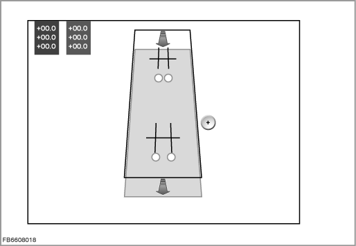
In the example below, the overlay must be shifted towards rear.
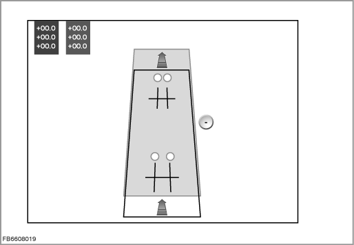
Shift the overlay on the y-axis. Shift the overlay to the left (plus direction) or to the right (minus direction) until the four crosses go through the four circles. In the example below, the overlay must be shifted to the right.
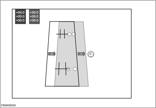
In the example below, the overlay must be shifted to the left.
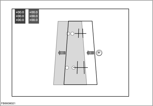
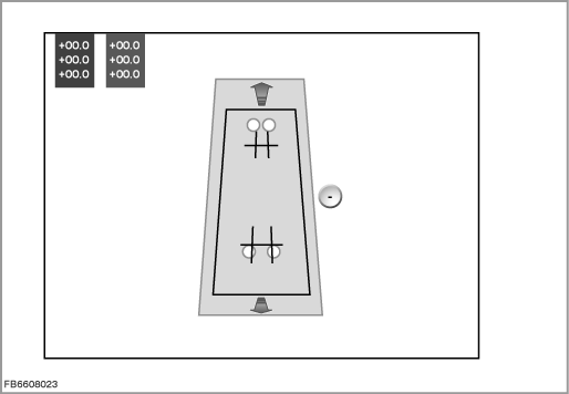
Shift the overlay on the z-axis. Shift the overlay upwards (minus direction) or downwards (plus direction) until the four crosses go through the four circles. In the example below, the overlay must be shifted downwards.
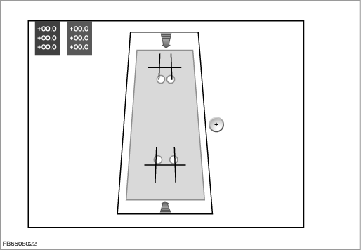
In the example below, the overlay must be shifted upwards.
Rotating on the x-axis, z-axis and around the centre of the camera image
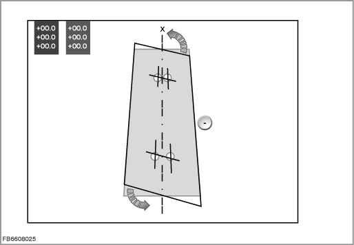
Rotate the overlay on the x-axis. Tilt the overlay to the left (minus direction) or to the right (plus direction) until the four crosses go through the four circles. In the example below, the overlay must be rotated to the right.
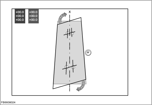
In the example below, the overlay must be rotated to the left.
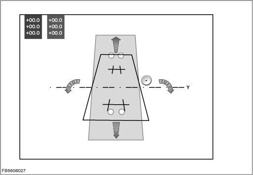
Rotate the overlay on the y-axis. Rotate the overlay towards rear (minus direction) or forwards (plus direction) until the four crosses go through the four circles. In the example below, the overlay must be turned towards rear.
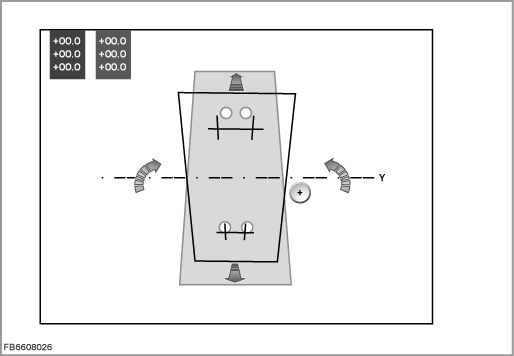
In the example below, the overlay must be turned forwards.
Rotate the overlay around the centre of the camera image. The settings depend on values of the x-axis and z-axis that have already been adjusted. This rotation can influence a rotation in the x-axis and z-axis. A rotation around the centre of the camera image is possible here. If the overlay has been shifted or rotated too far from the target, this change can place the overlay on the target. Thereafter, other changes (shift, rotate) can be made.
Completing the calibration
At the end of the calibration, the crossed must pass through the centre of the circles. The optimized alignment of the lines is achieved when the inner areas of the circles show through around the lines. The set calibration values are adopted into the rear view camera on confirmation.